
Let us understand how we can help you
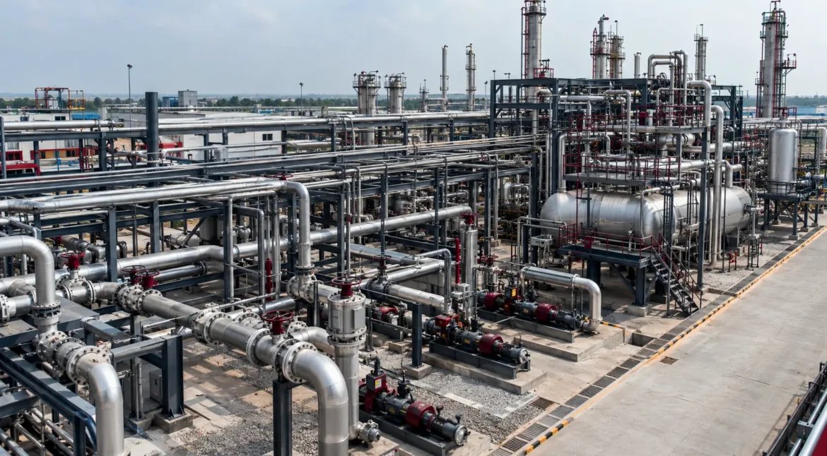
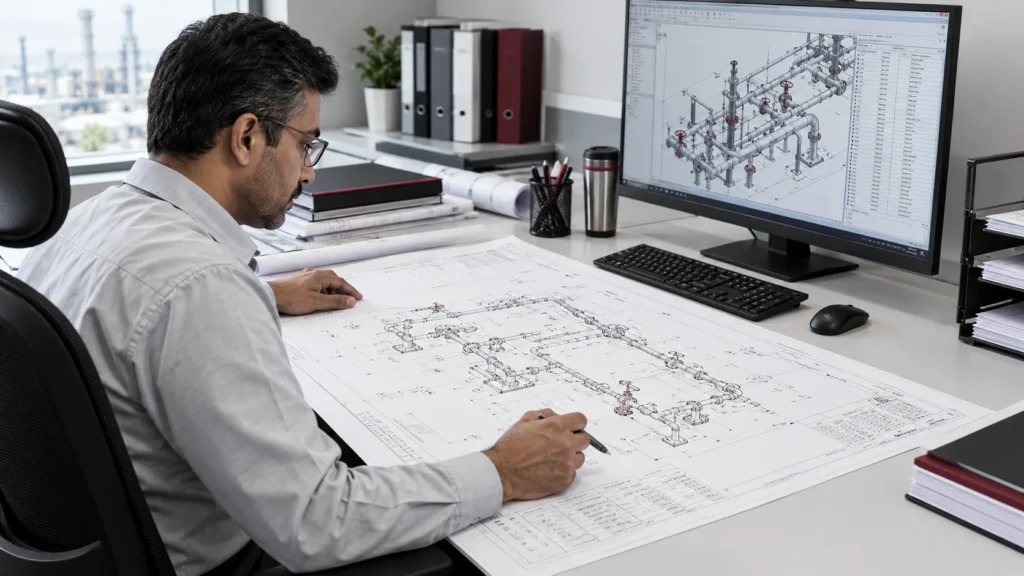
INDSAFE provides piping isometric drawing services for process plants and industrial facilities, supporting the detailed representation of piping systems for engineering coordination, fabrication planning and installation. Our approach focuses on translating approved piping layouts, Piping and Instrumentation Diagrams (P&IDs), piping specifications and other relevant engineering inputs into clear, coordinated isometric drawings.
Piping isometric drawings help communicate pipe dimensions, component locations, fittings, connections and other line-specific information required for project execution. The scope of each drawing is defined according to project requirements, available design information and applicable engineering specifications.
What Is a Piping Isometric Drawing?
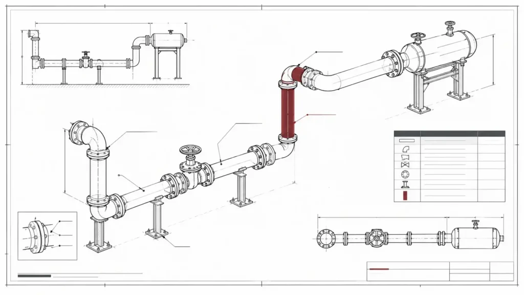
A piping isometric drawing is a technical representation of a piping line or section using an isometric projection to show its three-dimensional arrangement on a two-dimensional drawing. It communicates the geometry and component details of the piping system in a format that can support engineering review, material planning, fabrication and installation.
Depending on the project requirements, a piping isometric drawing may include pipe dimensions, line identification, fittings, valves, flanges, weld locations, connection details, elevations, material specifications and a bill of materials (BOM).
Unlike a Piping and Instrumentation Diagram (P&ID), which represents process equipment, piping connections, instrumentation and control-related information schematically, an isometric drawing provides a more detailed representation of the physical configuration of a piping line or section.
Our Piping Isometric Drawing Services
1. Piping Isometric Drawing Preparation
Preparation of piping isometric drawings using approved P&IDs, piping layouts, line lists, piping specifications and other available engineering information. Drawings are developed to represent the piping configuration, dimensions and components required by the agreed project scope.
2. Piping Fabrication and Spool Drawings
Preparation or development of piping fabrication and spool drawings where included in the project scope. These drawings may identify spool sections, component arrangements, dimensions, weld locations and relevant fabrication information required by the project.
The level of fabrication detail depends on the client’s requirements, fabrication practices and the engineering information available.
3. Piping Layout and Isometric Coordination
Coordination of isometric drawings with piping layouts, approved P&IDs, line specifications and relevant equipment connection information. This helps maintain consistency between the intended plant arrangement and the detailed representation of individual piping lines.
4. Material Take-Off and Bill of Materials
Preparation or documentation of piping component quantities and material information where required. Depending on the agreed deliverables, a bill of materials may include pipe lengths, fittings, flanges, valves and other specified components.
Material quantities should be reviewed against the applicable drawing revision, project specifications and agreed measurement basis. Procurement quantities may require additional allowances or checks outside the drawing-based take-off.
5. As-Built Piping Isometric Drawings
Updating piping isometric drawings to reflect verified installed conditions and approved plant modifications. This may involve reviewing available site measurements, marked-up drawings, existing documentation and other verified information.
The reliability of as-built drawings depends on the accuracy and completeness of the information used for verification. Site surveys or dimensional verification should be included in the agreed scope where required.
6. Piping Isometric Revision and Modification
Revision of existing isometric drawings to reflect approved changes in piping routes, equipment connections, component specifications or installation requirements. Drawing revisions should maintain appropriate document identification, revision status and traceability to the applicable engineering inputs.
Information Typically Shown on Piping Isometric Drawings
The information included in a piping isometric drawing depends on the piping system, project stage and client requirements. Typical drawing information may include:
Line identification: Piping line number, service identification and other required line references.
Dimensions and elevations: Pipe lengths, dimensional references, offsets and elevations necessary to communicate the piping geometry.
Piping components: Fittings, flanges, valves and other specified inline components.
Connections: Equipment nozzle connections, tie-in points and other relevant connection details.
Weld information: Weld locations, weld identification and spool breaks where required by the project.
Material specifications: Pipe and component material information, specifications and ratings as applicable.
Support references: Relevant pipe support locations or identifiers where required by the drawing scope.
Bill of materials: Component descriptions, sizes, quantities and other material information where included.
Drawing references: Sheet numbers, drawing identification, revision status and related references.
Not every isometric drawing contains all these elements. The required content should follow the project’s drawing standards, piping specifications and approved engineering documentation.
Our Piping Isometric Drawing Approach
1. Review of Engineering Inputs
Review available P&IDs, piping layouts, line lists, piping specifications, equipment connection details, design criteria and other relevant project documents.
2. Isometric Drawing Development
Develop isometric drawings using the approved piping arrangement and available dimensional and component information. Confirm the required level of detail according to the intended use of the drawings.
3. Engineering Coordination and Verification
Check drawing information for consistency with the available engineering inputs, including line identification, dimensions, components, material specifications and relevant connection details. Any discrepancies or missing information requiring clarification are identified for resolution.
4. Review and Revision
Incorporate agreed review comments and approved engineering changes. Maintain drawing identification and revision information to support document control and coordination with related project records.
5. Final Drawing Issue
Issue the agreed piping isometric drawings and supporting documentation in the specified format and revision status. Fabrication or installation release status should follow the client’s approval and document-control procedures.
Piping Isometric Drawings for New and Existing Facilities
New Industrial Facilities
For new facilities, piping isometric drawings support the detailed representation of piping lines developed from approved layouts, P&IDs and other engineering inputs. They can help communicate dimensions, component arrangements and material information required for fabrication and installation planning.
Existing Industrial Facilities
For operating facilities, isometric drawings may be developed or updated for piping modifications, equipment replacement, tie-ins, rerouting and other plant changes. Existing drawings, marked-up documents and verified site information are important inputs, particularly when the installed configuration differs from the original design.
Where required, site verification and as-built documentation should be defined as part of the project scope before final drawings are issued.
Piping Isometric Drawing Deliverables
Depending on the agreed scope, project requirements and available engineering inputs, deliverables may include:
Piping isometric drawings for specified lines or systems
Piping fabrication or spool drawings, where included
Drawing-based piping material take-offs or bills of materials
Revised piping isometrics for approved modifications
As-built piping isometric drawings based on verified information
Drawing registers, revision records and associated documentation, where required
Drawing formats, content requirements, approval status and deliverable quantities should be agreed at the beginning of the project.
Industries We Support
Piping isometric drawing services may support engineering and project activities across:
Oil and gas facilities
Chemical and petrochemical plants
Pharmaceutical and specialty chemical facilities
Power and energy facilities
Manufacturing and process industries
Other industrial facilities requiring detailed piping documentation
The applicable drawing requirements depend on the facility, piping service, project specifications and intended use of the drawings.
Why Choose INDSAFE for Piping Isometric Drawing Services?
Clear and coordinated piping documentation is important for communicating design intent and supporting project execution. INDSAFE approaches piping isometric drawing development with an emphasis on drawing consistency, dimensional clarity and alignment with the available engineering inputs.
Our approach focuses on:
Coordination with approved P&IDs and piping layouts
Clear representation of piping geometry and components
Attention to dimensions, line identification and material information
Drawing review and revision control
Support for new installations and existing plant modifications
Deliverables aligned with the agreed project scope and documentation requirements
The final engineering responsibilities, verification requirements and drawing approval process are established according to each project’s specifications and contractual scope.
Frequently Asked Questions
What is the purpose of a piping isometric drawing?
A piping isometric drawing represents the three-dimensional arrangement of a piping line or section on a two-dimensional drawing. It communicates dimensions, fittings, connections and other required details to support engineering review, fabrication planning, installation and material documentation.
What information is required to prepare piping isometric drawings?
Typical inputs include approved P&IDs, piping layout drawings, line lists, piping specifications, equipment connection details and applicable project drawing standards. Additional dimensional or site information may be required depending on the piping system and the intended use of the drawings.
What is the difference between a piping layout and an isometric drawing?
A piping layout shows the physical arrangement and routing of piping systems within a facility. A piping isometric drawing represents an individual piping line or section in an isometric projection, providing more detailed information about its geometry, dimensions and components.
What is the difference between a P&ID and a piping isometric drawing?
A P&ID is a schematic representation of process equipment, piping connections, valves, instrumentation and relevant control or safeguard elements. A piping isometric drawing provides a detailed representation of the physical arrangement of a particular piping line or section. The two documents serve different but complementary engineering purposes.
Do piping isometric drawings include a bill of materials?
They may. A bill of materials can list specified piping components and quantities shown on the drawing. Whether it is included, and how quantities are measured, depends on the project requirements and agreed deliverables.
Can piping isometric drawings be prepared for existing plants?
Yes. They can be developed or revised for existing facilities, including piping modifications, equipment changes and tie-ins. Reliable existing drawings and verified site information are important inputs when documenting the installed arrangement.
Are piping isometric drawings sufficient for piping stress analysis?
No. An isometric drawing can provide geometric and component information that may be used as an input to piping stress analysis, but the drawing alone does not establish that the piping system meets applicable stress or flexibility requirements. Stress analysis is a separate engineering activity when required by the project.
Which standards apply to piping isometric drawings?
Applicable requirements depend on the piping service, project specifications, governing piping code and drawing conventions adopted for the project. For example, ASME B31.3 may govern process piping design requirements within its scope, but it should not be treated as a universal drawing-preparation standard. The applicable codes and standards should be confirmed for each project.
Related Design & Engineering Services
Explore related INDSAFE services:
Design & Engineering Services for an overview of our industrial engineering capabilities.
Process Design Engineering Services for process calculations, process development and process engineering documentation.
P&ID Development & Engineering Services for piping and instrumentation diagrams and related engineering documentation.
Piping Layout Engineering Services for physical piping arrangements and pipe routing within industrial facilities.
Process Plant Design & Engineering Services for broader plant design and multidisciplinary engineering coordination.
Discuss Your Piping Isometric Drawing Requirements
Need piping isometric drawings for a new industrial project, fabrication planning or an existing facility modification? Contact INDSAFE to discuss your engineering inputs, drawing requirements and expected deliverables.