


An arc flash study is only as reliable as the electrical system data used to perform it. Arc flash study accuracy depends on having current and verified information about the electrical network, including single-line diagrams, available fault current, transformer and cable parameters, and protective device settings. When these inputs no longer reflect actual site conditions, incident energy calculations, arc flash boundaries and arc-rated PPE requirements may become inaccurate.
Key Takeaways
- Arc flash results are only as reliable as the data behind them. IEEE 1584-2018 provides the calculation methodology, not a guarantee of accuracy.
- The inputs that most often become outdated are the single-line diagram, short-circuit levels, transformer and cable data, and protective device settings.
- An outdated study can underestimate or overestimate the hazard. It is not automatically conservative.
- Review the study after any change that affects fault current or fault-clearing time, and at intervals not exceeding five years under NFPA 70E.
- Fix the process, not just the report: a change-management trigger helps keep the study current.
What Determines Arc Flash Study Accuracy?
An arc flash study estimates the thermal energy released in an arcing fault at specific electrical equipment. It determines the incident energy (cal/cm²) at a specified working distance and the arc flash boundary, providing information used to assess electrical hazards and select appropriate arc-rated PPE.
IEEE 1584-2018, Guide for Performing Arc-Flash Hazard Calculations, provides the calculation methodology. Within its applicable scope, it uses inputs such as:
- Nominal system voltage
- Available three-phase bolted fault current
- Arcing current, including the minimum arcing current variation considered by the methodology
- Protective device fault-clearing time
- Electrode configuration and conductor gap
- Enclosure type and dimensions
- Working distance
Two particularly important inputs are fault current and protective device clearing time. These depend on the electrical network configuration and protection settings.
If either is outdated, the calculation output may no longer represent the actual installation, regardless of how accurately the software performs the calculations.
How Outdated Electrical Data Affects Arc Flash Results
1. How Outdated Single-Line Diagrams Affect Arc Flash Study Accuracy

The electrical single-line diagram is the basis of the system model. When transformers, motors, feeders, panels or bus-tie arrangements are added or changed without updating the diagram, the model may leave out actual equipment or show connections that no longer exist.
Common gaps include:
- New transformers or switchgear not shown on the drawing
- Additional motors or feeders connected to existing boards
- Changed bus coupler or tie-breaker arrangements
- Modified normal and standby supply arrangements
Impact: Fault currents and downstream arc flash results are calculated using a network that no longer accurately represents the installation. Verify the SLD against the actual electrical system before using it.
2. The Impact of Incorrect Fault Current Data on Arc Flash Calculations
Available fault current can change due to:
- Transformer replacement or a different rating or impedance
- Changes in the utility supply or generator capacity
- Changes in cable size, length or number of parallel paths
- Changes in the number of sources feeding the bus
Impact: The bolted fault current is used to determine arcing current, which influences protective device response and incident energy.
Higher fault current does not always mean higher incident energy. A lower arcing current can cause a protective device to operate in a slower region of its time-current characteristic, resulting in a longer clearing time and potentially higher incident energy.
Therefore, both fault current magnitude and protective device response must be evaluated together. Relevant maximum and minimum operating conditions should also be considered.
3. Why Protective Device Settings Matter for Arc Flash Study Accuracy

Arc duration is influenced by the protective device, so its settings can significantly affect incident energy.
An arc flash study requires information such as:
- Manufacturer, model, ratings and trip unit type
- Long-time, short-time, instantaneous and ground-fault settings, where applicable
- Time-current characteristics
- Relay settings and associated breaker opening and clearing times
Example: A circuit breaker’s instantaneous pickup setting is raised during maintenance to prevent nuisance tripping. If the study continues to use the old setting, the modelled clearing time may be shorter than the actual clearing time, potentially making the labelled incident energy significantly too low.
Impact: Incorrect clearing time can substantially change incident energy even when available fault current has not changed. Verify installed settings at the device rather than relying exclusively on old reports.
4. How Transformer and Cable Changes Affect Incident Energy Calculations
Transformer impedance and cable impedance influence how fault current flows through the electrical distribution network.
Replacing an existing cable with a larger conductor can reduce feeder impedance and may increase downstream fault current. Similarly, a transformer with a different percentage impedance can change fault levels across the connected network.
Impact: If the electrical model retains the original parameters, the short-circuit results and subsequent arc flash calculations may no longer represent the actual plant.
5. The Role of Operating Conditions in Arc Flash Study Accuracy
Industrial facilities often operate in more than one electrical configuration. Examples include:
- One transformer operating instead of two
- Bus coupler open or closed
- Generator operating independently or in parallel with utility supply, where permitted
- Alternative incomers supplying different sections of the distribution system
Impact: Each configuration can produce different fault currents and protective device responses. A study based on only one configuration may overlook another condition that produces a higher incident energy.
Identify the relevant operating scenarios and evaluate those that could affect the results.
What Can Go Wrong: Underestimated, Overestimated or Mislocated Hazards
| Error in the study | Possible consequence |
|---|---|
| Clearing time assumed shorter than actual | Underestimated incident energy; arc-rated PPE may be inadequate |
| Fault current or device data based on incorrect assumptions | Overestimated or underestimated incident energy, depending on the actual conditions |
| Incident energy calculated incorrectly | Incorrect arc flash boundary, affecting access controls and safe working distances |
The arc flash boundary is the distance from the prospective arc source at which incident energy is calculated to be 1.2 cal/cm² under the applicable methodology.
Outdated data does not produce a consistently safe or consistently conservative result. It produces an unreliable assessment.
Practical Example: Three Small Changes, One Unreliable Study
A facility completed an arc flash study several years ago. Since then:
- A transformer was replaced with a different rating and impedance.
- A new motor feeder was added to the distribution board.
- A breaker trip setting was changed for operational reasons.
- The SLD was not revised, and the old equipment labels remained in place.
Each change can affect an input to the assessment. The transformer modification can change available fault current, the new feeder can change the network model and potentially introduce motor fault contribution, and the trip setting can change fault-clearing time.
Together, these changes mean the labels may no longer accurately represent the electrical hazard.
Even limited modifications can justify a technical review of the existing study.
When Should You Review or Update an Arc Flash Study?
Review the study whenever a change could affect fault current, arcing current, protective device operation or other relevant calculation inputs.
| Change in the electrical system | Potential impact on the study |
|---|---|
| Transformer replacement | Changes impedance and available fault current |
| Breaker or relay setting change | Changes fault-clearing time |
| New generator or power source | Changes fault contribution and operating scenarios |
| New motor or feeder installation | May change network topology, impedance and motor fault contribution |
| Cable replacement or rerouting | Changes network impedance |
| Bus coupler or tie configuration changes | Changes fault paths and operating scenarios |
| Utility supply modification | Changes available fault current at the point of connection |
| Switchgear replacement | Changes equipment characteristics and calculation inputs |
Periodic review: NFPA 70E requires the incident energy analysis to be updated when electrical distribution system changes could affect the results and reviewed for accuracy at intervals not exceeding five years.
As of November 2026, NFPA 70E-2027 is the current published edition. The applicable adopted edition and exact requirements should be checked when establishing a facility’s review programme.
The five-year interval is a maximum review interval, not permission to continue using known-inaccurate results. Significant electrical modifications may require an earlier reassessment.
Considerations for Industrial Facilities in India
Industrial facilities in India should also consider applicable statutory electrical safety requirements, including the Central Electricity Authority (Measures relating to Safety and Electric Supply) Regulations, 2023, as amended.
Regulation 21 addresses the handling of electric supply lines and apparatus and includes provisions for protective equipment, tools and devices to protect personnel against electrical injury, including arc flash.
IEEE 1584-2018 can be used as a technical calculation methodology within its applicable scope, alongside relevant Indian statutory requirements and site-specific electrical safety procedures.
The CEA 2026 Amendment Regulations have a commencement date of 1 April 2027; their provisions should be considered according to their effective date and applicability.
What Data to Verify Before an Arc Flash Study
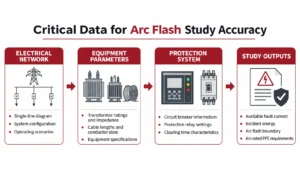
A. Electrical network
- Current single-line diagrams
- Utility supply and available fault level
- Transformer ratings and impedance
- Generator ratings and operating arrangements
- Cable sizes, lengths and conductor materials
- Bus and feeder configurations
- Normal and alternate operating scenarios
B. Protective devices
- Breaker make and model, fuse ratings and relay details
- Installed trip units and actual settings
- Time-current curves
- Breaker opening and total clearing times
C. Equipment
- Switchgear and panelboard ratings and voltage levels
- Busbar and conductor arrangements
- Electrode configuration
- Enclosure dimensions
- Working distances
D. Records
- Modification and equipment replacement history
- Protection setting change records
- Commissioning and test documentation
- Updated utility fault-level data
Check the data for consistency before incorporating it into the model. Where information cannot be verified, state the assumption, justify it and document it. Do not present unverified values as confirmed site data.
How to Keep Arc Flash Calculations Reliable: 8 Steps
- Collect data: Gather SLDs, equipment ratings, transformer and cable information, and protective device details.
- Verify on site: Compare records with equipment nameplates, installed devices, actual trip settings and feeder arrangements.
- Build or update the model: Incorporate verified information and all relevant electrical operating scenarios.
- Run short-circuit analysis: Calculate available bolted fault current at each relevant equipment location under applicable maximum and minimum operating scenarios.
- Review protection coordination: Determine clearing times at the relevant arcing currents. Evaluate the minimum arcing current variation required by IEEE 1584-2018 to identify whether it results in a longer protective device operating time and higher incident energy.
- Calculate incident energy and arc flash boundaries: Apply IEEE 1584-2018 within its applicable scope. Verify that the system voltage, conductor gap and equipment enclosure configuration fall within the model’s applicable range.
- Review results and update labels and reports: Check the results for engineering consistency and revise equipment labels and documentation wherever necessary.
- Set up change management: Make equipment modifications, replacements and protection setting changes trigger a review of whether the existing arc flash study needs updating.
Make the Arc Flash Study Part of an Ongoing Safety Programme
An arc flash study should not be treated as a one-time compliance exercise. Assign clear responsibility for:
- Maintaining current single-line diagrams
- Recording electrical modifications and protection setting changes
- Reviewing changes in available fault levels
- Evaluating whether a change requires a study update
- Keeping reports and equipment labels current
- Giving electrical personnel access to current safety information
A structured approach helps maintain consistency between the actual electrical installation, engineering calculations and workplace electrical safety practices.
Conclusion
Maintaining arc flash study accuracy requires more than performing calculations correctly. It depends on using verified electrical system data, accurate protective device settings, appropriate operating scenarios and a documented process for managing system changes.
As electrical networks evolve, previously calculated incident energy levels and arc flash boundaries may no longer reflect actual site conditions. Changes to transformers, cables, switchgear, fault levels or protection settings can affect the results of an existing study. Periodic reviews and updates following significant electrical modifications are therefore essential to maintaining reliable results.
A properly maintained arc flash study helps facilities make informed decisions about electrical hazards, select appropriate arc-rated PPE, establish safe work practices and support compliance with applicable electrical safety requirements. The reliability of an arc flash study ultimately depends on how accurately it represents the electrical system as it exists today.
Is Your Arc Flash Study Still Valid?
INDSAFE provides arc flash studies, short-circuit analysis, protective device coordination and electrical risk assessments for industrial facilities.
Through systematic electrical data collection, site verification and engineering analysis, INDSAFE helps facilities evaluate electrical hazards and obtain assessment results that reflect the electrical system being studied.
Request an Arc Flash Study / Electrical Risk Assessment.
Website: https://indsafe.in/
Email: consult@indsafe.in
Frequently Asked Questions
Why can arc flash calculations become inaccurate?
They become inaccurate when the electrical system data used no longer matches the installation. Changes in transformers, fault current, cables, operating configurations and protective device settings can affect incident energy and arc flash boundaries.
How often should an arc flash study be updated?
Review it whenever a change could affect the results. NFPA 70E also requires periodic review at intervals not exceeding five years. Significant modifications should not wait for the next scheduled review.
Does changing a circuit breaker setting affect incident energy?
Yes. Breaker and relay settings affect fault-clearing time. Arc duration is an important factor in incident energy calculations, so a modified setting can change incident energy and the arc flash boundary.
Why is an updated single-line diagram important for an arc flash study?
It defines the network model, including transformers, feeders, power sources, breakers and distribution arrangements. An outdated SLD can result in an incomplete or incorrect electrical system model.
Can outdated data lead to incorrect PPE recommendations?
Yes. Incorrect fault current or protective device information can produce inaccurate incident energy estimates. PPE selected using those results may not adequately reflect the actual electrical hazard.
What information is required for an arc flash study?
Important information includes single-line diagrams, available short-circuit current, transformer ratings and impedance, cable parameters, protective device settings, equipment configuration, enclosure dimensions and working distances.
What standards are used for arc flash calculations?
IEEE 1584-2018 provides the calculation methodology for arcing current, incident energy and arc flash boundaries within its applicable scope. NFPA 70E provides guidance on electrical safety practices, arc flash risk assessment, incident energy analysis and review requirements.